| Amapi 7 Pro Tutorial:
Building the Santa Maria with NURBS
Carl E. Schou
June 30, 2004
| |
|
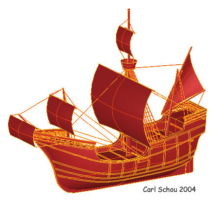
Santa Maria in Red
For this month's visit to the digital domain, we are going to
build a model of Christopher Columbus' ship the Santa Maria, using
the NURBS tools available in Amapi 7 Pro. The image above
shows the untextured model of the Santa Maria as seen in Amapi's
modeling window. We will start with a brief history of the
ship and mention some sources for modeling reference materials, then
present a strategy for building the ship with Amapi Pro's NURBS
tools, before beginning the actual modeling process. Some of the images used in this
tutorial act as
links to larger versions of those images. If this larger image doesn't appear
at full size, then let your mouse hover over the image and click on the
magnification button that appears. |
| |
|
Brief History of the Santa Maria
The three ship fleet of Christopher Columbus set out from the
port of Palos on the coast of southern Spain on August 2nd, 1492.
Columbus' flag ship the Santa Maria was accompanied by the Nina and
the Pinta, and the total crew complement was 88 men. After a
brief stopover for repairs in the Canary Islands, the fleet traveled
2400 miles and arrived in the Bahama Islands on October 12th.
On December 24th, the Santa Maria ran aground on a reef along the
coast of Cuba while being piloted in calm waters by an inexperienced
ship's boy, and had to be abandoned. The timber from the ship was
used to build a fort named Navidad and a garrison of thirty nine
crew members were left behind to man it, since there wasn't room to
carry all of the crew members back to Spain on the remaining two
ships. When Columbus returned to the New World less than a year
later, he found that the fort had been destroyed and there were no survivors
from the original garrison.
No one is absolutely sure just what the Santa Maria looked like
since there are no surviving building plans. The Santa Maria
is thought to have been approximately 80 feet long, 25 feet wide,
and 200 tons. Using written accounts of the day, together with
illustrations from the time, the kind of ship has been narrowed down
to one of two similar types, the Caravel, or the Nao. The
model covered in this tutorial is based on the Nao design. |
| |
|
Reference Material for Modeling
Probably the best source images of the Santa Maria are in a book
that is now out of print, but available through online used
bookstores such as Alibris. The book is called "The Ships of
Christopher Columbus", written by Xavier Pastor, ISBN 1-55750-755-4.
Information on Alibris, and sources for blueprints, are available in
the Related Links section at the end of this tutorial. |
| |
|
Strategy for Building an Old
Sailing Ship
(1) Research the ship you intend to build, get detailed images
from several different views if possible.
(2) Build the hull from NURBS, taking advantage of symmetry and
cloning. In this case, the Manifold tool in Amapi 7 Pro is
used. NURBS surfaces of the deck, stern, and sides are created
and arranged to completely enclose a volume shaped like the ship's
hull. The Manifold tool generates a 3D NURBS surface from this
enclosed volume.
(3) Set the decks down slightly into the hull.
(4) Add the keel, rudder, railings, masts, and Crow's Nest.
(5) Build the sails from NURBS surfaces.
(6) Create the rigging for the masts and sails.
(7) Build the external structural support ribs for the hull.
These are cut from a duplicate of the hull to ensure that they
follow the hull shape. |
| |
|
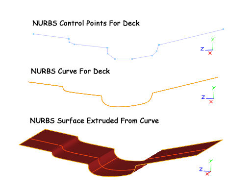
Build the Deck
To build the deck, select the pen tool and draw the NURBS line as shown
below. For sharp corners, use closely spaced control points.
For smooth, slowly changing curves keep the controls far apart.
To create the NURBS surface for the deck, make sure the top level of
the Dynamic Geometry is active, select the Extrude tool, then click
the curve and drag the mouse to extrude the surface out from the
working plane. You will probably have to press the space bar a
couple of times to get the correct extrusion mode which keeps the
extrusion size constant. |
| |
|
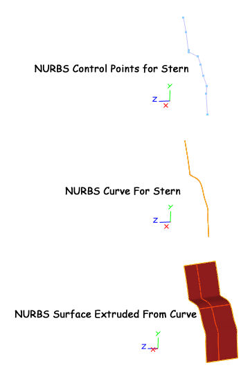
Build the Stern
The stern is built the same way as the deck, by creating a NURBS
curve, then extruding it out as a surface as is shown below. |
| |
|
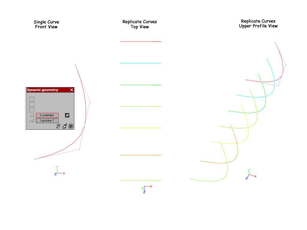
Create the Curves for the Hull
Using the Pen tool, create a line with 4 points as shown below
left. Switch to a top view and make sure the top level of
Dynamic Geometry is active, then make six additional copies of the
line spaced as shown below center and right. Click on the
image below to see the full sized version. |
| |
|
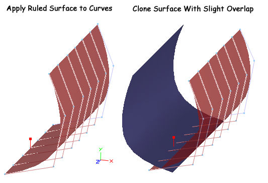
Apply Surface to Curves, Then Clone
Click the Ruled Surface tool, then click the top tip of each
curve going from front to back. Press Enter to validate and create
the surface as shown below left. Click the Symmetry tool with
the option set to Clone to produce the other side as shown below
right. Note that the top level of Dynamic Geometry must be
active to mirror the entire surface. The bottom level was
active for the illustrations so that the control points would be
visible. |
| |
|
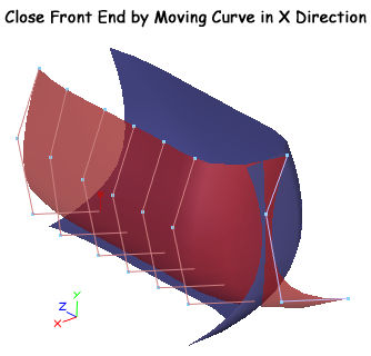
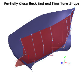
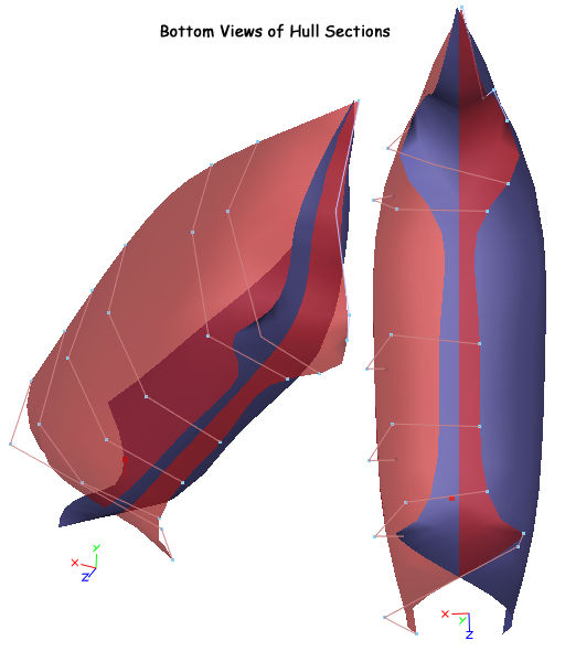
Move Control Points to Shape the
Hull
Move the control points as shown in the next three images to
approximate the shape of the hull. The front end is completely
closed, while the stern end is left partially open. |
| |
|
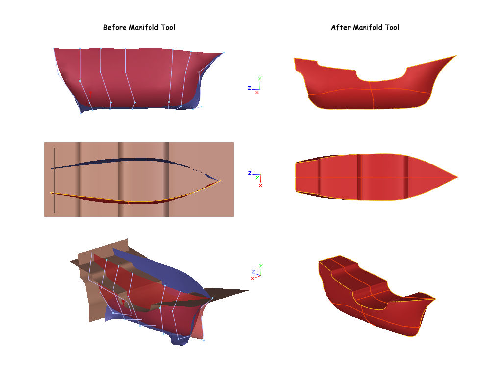
Combine Pieces and Apply Manifold
Tool
Next, put together the Deck, Stern, and Hull pieces as shown
below left in side, top, and profile views. Make sure that the top level
of Dynamic Geometry is active and that the surface normals of
each piece are directed outwards. This may be done by double
clicking a piece to bring up its Information window, then clicking
on Orient Normals. The orientation may be changed by clicking
the cube at the base of the Normal arrow on the piece in question.
It is also necessary to make sure that the enclosed volume is
"watertight", meaning that there are no openings to the space that will be
used to create the model. If these things look correct, then
click on the Manifold tool, click on each piece, and validate.
You should have a model similar to that shown below right.
Click on the image below to see the full sized version. |
| |
|
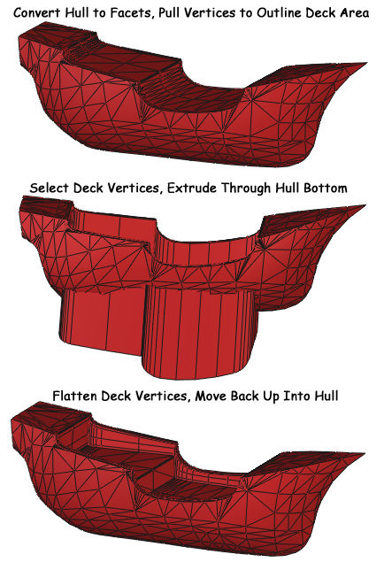
Set Decks Down Into Hull
There are many different methods that may be used to recess the
deck areas into the hull. Since
the model was going to be eventually converted to polygons, it was
decided to tessellate the hull now, then recess the deck by
manipulating vertices. Select the hull, and convert it from NURBS to polygons by completely collapsing the
Dynamic Geometry. The resulting polygons are triangles instead
of quads since the Crack Free NURBS option was chosen in the
preferences. Pull the deck vertices to outline the deck edges,
then select and extrude the deck facets through the bottom of
the hull using the Sweep by Block option. Separately flatten
the two sections of the deck by decreasing their vertical size. Finally,
move the
deck sections back up into the hull as shown below. |
| |
|
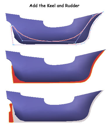
Add the Keel and Rudder
Use the Pen tool to draw a closed outline for the keel as shown
below. Select the curve, extrude it out a short distance
perpendicular to the working plane, then close the ends to produce
the keel. Use the same process to build the rudder. |
| |
|
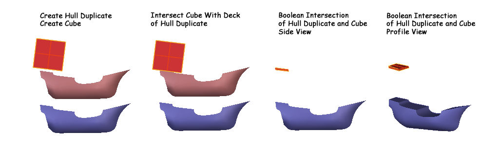
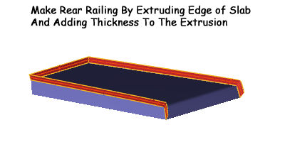
Cut Slab for Rear Railing Base
Object
Follow the process shown below to create a slab which will be
used to create the rear rails. Using the slab cut from a copy
of the hull allows you to work with something identical in shape to
the hull without having to worry bout damaging the original hull
object. Click the image to see
the full sized version. |
| |
|
Select the top edge of the rear deck
slab and extrude it out a short distance with the Sweep by Block
option active, then add thickness to the extrusion as shown below.
Trim off the downward curving tips, and you'll have a set of
handrails that match the shape of the rear deck. |
| |
|
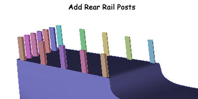
Back at the rear deck area of the actual
hull, add the vertical posts to support the railings as shown below.
|
| |
|
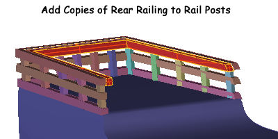
Add copies of the railings to the posts.
In the image below, the position of some of the posts still needs to
be adjusted. |
| |
|
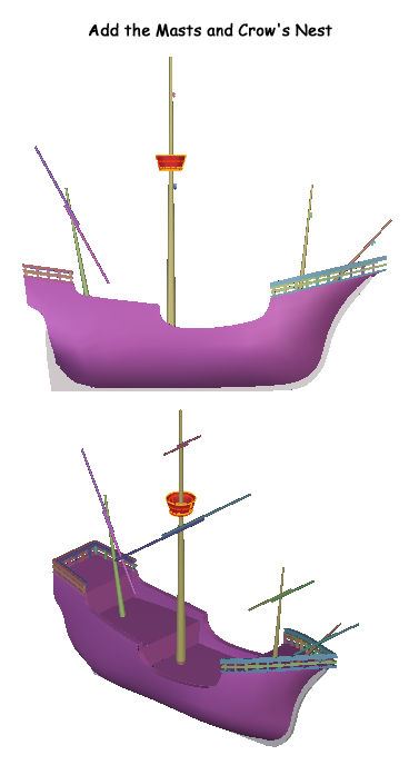
Add the Masts and the Crow's Nest
Simple tapered cylinders were used for the masts. The
Crow's Nest was made by drawing a NURBS circle with the Pen tool and
extruding it into the proper shape. |
| |
|
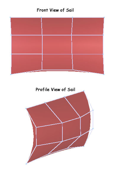
Making the Sails
The first sail was made by drawing a NURBS line with the Pen tool
with four control points. This line was copied three times. A
Ruled Surface was then applied between the lines. In the
Dynamic Geometry, the Ruled Surface level was collapsed to produce a
NURBS shape. The control points were pulled out to produce the
sail shape in the images below. |
| |
|
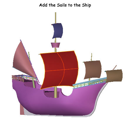
Add the Sails to the Ship
Five sails were made by copying the original sail shape from the
previous step. These were individually shaped and added to the
masts as shown below. The triangular lateen sail on the mizzen
mast at the rear of the ship required the most extra shaping. |
| |
|
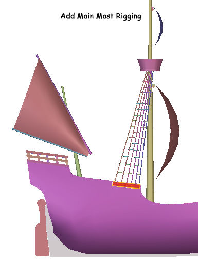
Add the Main Mast Rigging
The rigging was made from long thin cylinders running from the
side of the hull to the Crow's Nest as shown below. A cube was
added to the hull to act as an attachment point for the rigging.
The rigging for the right side of the ship was modeled first. |
| |
|
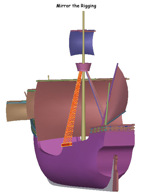
Mirroring the Rigging
The rigging on the right side of the ship was selected, then
mirrored using the Symmetry tool with the Cloning option turned off. |
| |
|
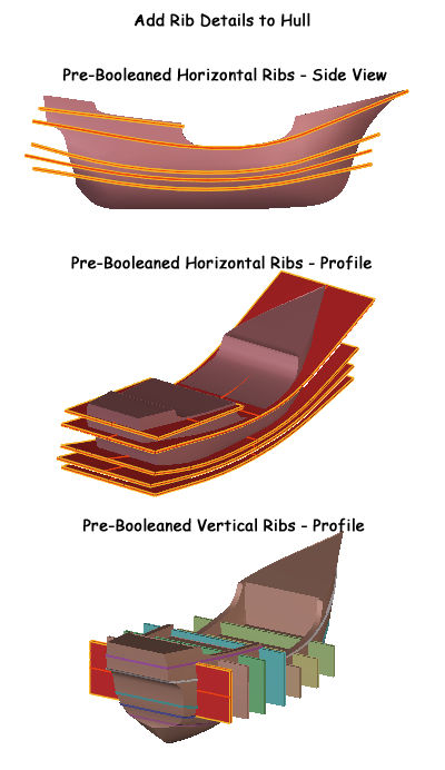
Adding Rib Details to the Hull
Next we will create the support ribs visible on the outside of
the hulls of many old sailing ships. A copy will be made of
the hull, and slabs corresponding to the ribs will be Boolean cut
from the hull copy. The ribs, which already follow the shape
of the hull, will be thickened a bit, then added to the original
hull.
To make the horizontal ribs, a set of five curved NURBS lines
were drawn with the Pen tool following the general curve of the hull
copy when seen from the side. These curves were extruded out
from the working plane to create NURBS surfaces the same way that
the deck and stern pieces were created at the start of the tutorial.
The same process was used to create the seven vertical ribs
The screenshots below show the horizontal and vertical rib slabs
prior to being Boolean subtracted from the hull copy. |
| |
|
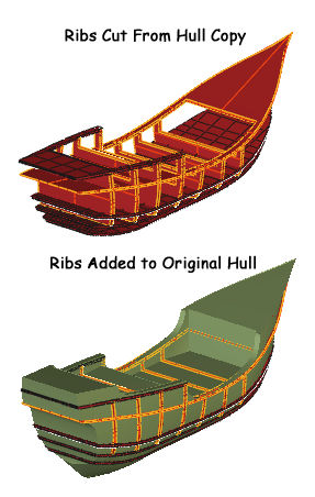
After a little bit of thickness was
added, the rib surfaces were Boolean intersected with the hull copy
to produce ribs that fit the hull perfectly. Extra thickness
was added to the ribs to make them stand out from the hull a bit.
The ribs were then added to the original hull as shown below. |
| |
|
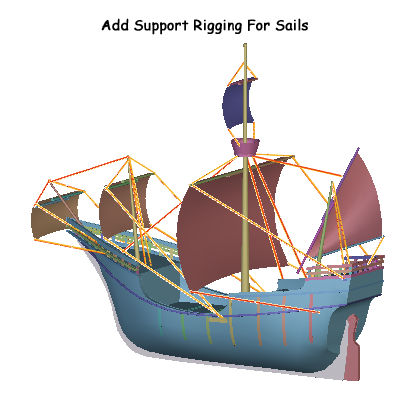
Add the Support Rigging for the
Masts and Sails
Very thin cylinders were added to create the support rigging
between the masts and sails. In the image below, the main mast
rigging we already created has been hidden for illustrative
purposes. |
| |
|
Where Do We Go From Here?
At this point, we have a very basic model of the Santa Maria that
has hopefully captured most of the essentials. Parts that
could be added to the model include flags and banners for the masts,
ladders for moving between the deck levels, and an anchor to keep
the ship in place. After completing the modeling portion of
the project, it needs to be exported for UV mapping, texturing, and
rendering in a scene, but that's a project for another day. |
[RETURN TO TUTORIALS]
Copyright © 2004,
Carl E Schou, All Rights Reserved |