| Amapi Tutorial:
Building an Easter
Island Statue From Photographs
Carl E. Schou
August 31, 2003
|
|
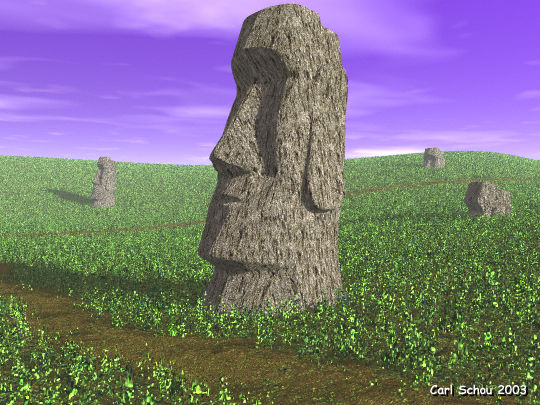
The Watchers
of the Years
The image above depicts
some of the giant stone statues of Easter Island in the south
Pacific. It was
rendered in Bryce using a model created in Amapi Designer 7 from
reference photographs. This tutorial will cover the use of
reference images in Amapi as well as the construction of the statue. We
will start with a little bit of background about Easter Island, then
outline the strategy for this project before starting
construction. After the model is built, we will take a look
how the rest of the image was made with a focus on the terrains and
the textures. |
|
|
The History
of the Statues
Easter Island was originally settled around
400 AD and was called "The Navel of the World" by the
original inhabitants. The name Easter Island was coined by
the European explorers who discovered the island on Easter Sunday
in 1722. Today, the island is known locally as Rapa
Nui. It is extremely remote, located over 2000 miles from the
nearest population center. It is also the home of the giant
enigmatic stone statues known locally as Moai.
The late archaeologist and explorer
Thor Heyerdahl, famous for the Ra and Kon-Tiki ocean voyages, said
that Easter Island originally had two
social classes. The
members of the ruling class were distinguished by their long ears
which had been stretched with weights or earrings as a sign of
nobility. The servant
class built the statues as monuments to the nobility, and the
long ears can still be seen in the statues.
In the process of building the monuments, the island was
stripped of trees and other resources, and the social order collapsed.
Many of the
statues were then toppled over the years, and only recently have
been they been restored to their original positions. The
Moai statues consist of a head and body, though in many cases they
are partially buried from centuries of erosion, leaving just the
head sticking out of the ground. The Moai vary in size, with
the average being 14.5 feet (4.5 meters) tall and weighing 14
tons. The larger Moai were up to 33 feet (10 meters) tall
and 80 tons. The
largest, about 65 feet tall, was never completed. The work
on this giant may have stopped when the uprising occurred. |
|
|
Strategy for
Modeling From Photographs
Inserting Reference
Photographs
Get the Reference Images - at least a front and side view at
the same scale are required.
Import the Images as Backdrops Use
orthogonal view instead of perspective view to minimize distortion. Building
the Model The object is symmetrical,
so model one half of the object and
mirror it later to complete the model. Chamfer
the sharp edges to preserve them during smoothing and rendering. Mirror
the half model and weld the two halves together. Smooth
the model if desired. |
|
|
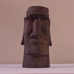
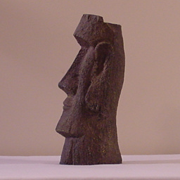
Get the Reference Images
You are going to need front and side views of the
object you plan to model, preferably at the same scale. If
you plan on building the Easter Island statue, the front and side
view photographs of the statue shown below are free for any
non-commercial use. Just right
click on them and use the Save As function to copy them to your hard drive for use as reference images. The
images are of a scale model of the head of
one of the Moai, purchased through eBay for this project, and photographed at the same distance to keep the
scale constant. If you make your own images, you will want
to get as far away from your model as is practical, then zoom in
on it to minimize distortion in the images due to perspective
effects. In general, the longer the focal length of your
camera lens, the less distortion you will get. |
|
|
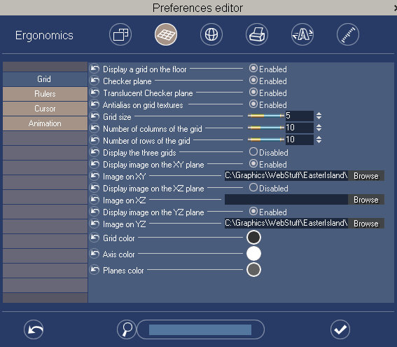
Import Images
as Backdrops
To import the images into Amapi for
use as reference backdrops, press Alt+P to open the Preferences
Editor and click on the second icon in the top row to bring up the
Ergonomics section. Set the controls to match those
shown in the image below. For the Image on the XY plane, use
the browser to load the front view. Similarly, use the
browser to load the side view into the YZ plane. |
|
|
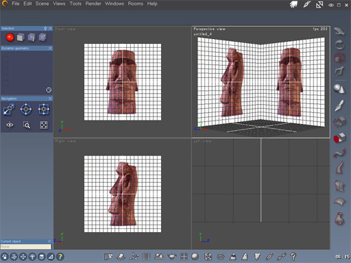
When you are
finished loading the backdrop images, set your interface for a
quad layout with a Front view at the lower left window and a Right
view at the lower right window. You should see something
like the screen shot image below. An orthogonal
view was used instead of a perspective view to minimize distortion
when modeling. Note also that the contrast and brightness of
the reference images was increased using PhotoShop. |
|
|
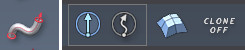
The
Tessellation Tool
To cut facets into the model, we will
be using the Tessellation tool. To access this tool, press the
Tessellation icon shown below left, from the Modeling Tool
Palette. Set the options as shown below right by selecting
the fifth icon for Multi-Slice Tessellation.
|
|
|
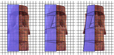
Modeling the
Statue From a Cube
To begin the
modeling process, a cube was created and its size was adjusted to
fit the left side of the head when viewed from the front, as shown
at below left. Faces were cut with the Tessellation tool
(below center) and the outer face was sloped to match the image
(below right).
|
|
|
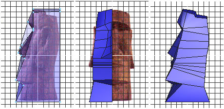
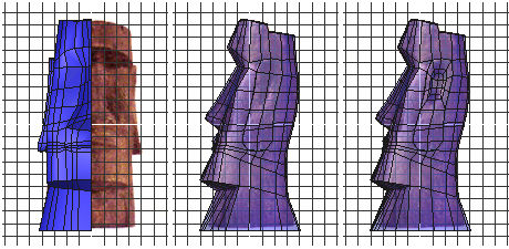
Next we switch
to the side view and begin moving the available vertices to
roughly line up the edges with the reference image ( below
left). Back in the front view, we cut more faces for the
nose and mouth with the Tessellation tool (below center).
This process is continued in the side view to ensure that all of
the polygons are four sided (below right). |
|
|
Still more
faces are cut for the face and the ear as shown below. |
|
|
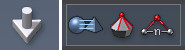
The Extrusion
Tool
To extrude the ear, we will be using
the Extrusion tool. To use this tool, select the facets you
want to extrude, then press the Extrusion icon shown below left,
from the Construction Tool Palette. Set the options as shown
below right by selecting the straight block extrusion. Press
Enter to start the extrusion process and tap the spacebar a few
times to toggle between the different extrusion modes.
|
|
|
Extruding the
Ear
More facets
were cut for detailing, and the facets for the ear were extruded
outward as a block (below left and center). The indentation
in the ear was produced by selecting the top six facets of the ear
and extruding them as a block three times while decreasing the
size and varying the position (below right).
|
|
|
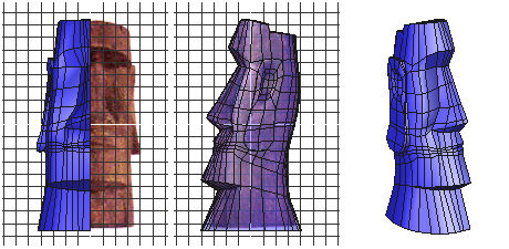
A last bit of
detailing was added and the vertex positions were tweaked to get
the three views shown below. |
|
|
Chamfer Edges
Before Smoothing
Before smoothing the model, we will
need to chamfer the hard edges to preserve the angular shapes of
the statue. Otherwise, applying smoothing will probably turn
your model into Mister Potato Head. Even if you decide not
to apply smoothing in Amapi, chamfering the edges will help to
preserve the model's appearance in programs like Poser which
automatically smooth over edges when rendering. To
use the Chamfering tool, select the edges you wish to chamfer,
then click the icon shown below left which is located in the
Modeling Tool Palette. Select the option shown below center
highlighted in blue. Below right we see the parameters,
where the range is set to 1 to minimize the geometry that is
added, and the radius is set to give the desired spacing between
the original selected edge and the new edges created by the
chamfering. |
|
|
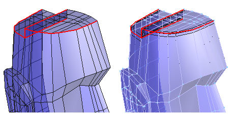
The
illustration below shows the edges along the top of the head
selected before chamfering (left) and after chamfering
(right). This process was repeated along the edges of the
eyes, ears, nose, lips, and jaw. |
|
|
Mirror the Model
Before mirroring and welding the
model, you will need to make sure the edge going down the
centerline is completely flat. To do this, select all of the
vertices on the centerline all of the way around the model, then
click on the Size tool. In the Parameters window that opens
up, the size in the X direction should be equal to zero.
To mirror the model, click on the
Symmetry icon shown below left, which is located in the Assembly
Tool Palette. Accept the default options shown below center,
and set the parameters to mirror in the +X direction as shown
below right. Press Enter to validate the mirroring. |
|
|
Weld the Model
To weld the model, press the Weld
icon shown below left, from the Assembly Tool Palette. Set
the options as shown below right. Left click on one half of the model, then
hold the shift key down and left click the other half so that both
halves are selected. Validate the weld by pressing the Enter
key. |
|
|
Smooth the Model
To smooth the model, click on the
smooth icon shown below left, which is located in the Modeling
Tool Palette. Accept the default options shown below center,
and set the parameters for a range of 1 as shown below
right. Press Enter to validate the mirroring. |
|
|
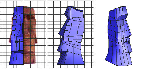
The image
below left shows the model after chamfering, mirroring, and
welding. The smoothed, finished model is shown below center,
and a textured render is shown below right. |
|
|
The Rest of
the Picture
The image at the top of
this tutorial, called The Watchers of
the Years, was rendered in Bryce. The ground was made up of
four identical terrains stacked one atop the other, with a ground
texture applied to the bottom-most terrain, and a vegetation texture
with randomized transparency applied to the rest. The top two
terrains also had low amplitude high frequency noise added to their
height maps and the walk path was cut into these two terrains using
the Bryce Terrain Editor.
The textures used for the
four statues are tiled variations of an image of one of the huge Sarsen,
or Standing Stones, at Stonehenge in Salisbury, England, UK. A UK based artist
and friend named Strike photographed the Sarsen while vacationing
with his wife, and I processed the image
through the TextureMaker program to produce a series of seamlessly
tiled images. My thanks to Strike for the use of his fine
image. |
[RETURN TO TUTORIALS]
Copyright © 2003,
Carl E Schou, All Rights Reserved |