Build a Battle Axe in
OpenFX
Carl E Schou
May 31, 2002
| |
|
Chop Down
Modeling Costs With OpenFX
Need a bargain on a 3D
Instrument of Persuasion for your next encounter with Orcs or Goblin
Hordes? Try building it in OpenFX.
OpenFX is a suite of
programs with modeling, animation, and rendering capabilities.
It is the open-source version of the commercial product known as
SoftF/X which is no longer available. You can download OpenFX
for free using the links at the end of this tutorial.
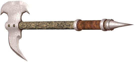
The battle axe pictured
above was modeled in OpenFX, grouped in Poser, and rendered in Bryce
using procedural textures. Alternately, you can do the
grouping in UVMapper, which is also a free utility.
|
| |
|
Pros and Cons
of OpenFX
The best thing about OpenFX is probably
the price. OpenFX lets you create
models right at the nuts and bolts level. If you're just
starting out, all of the hands-on
experience you get working with OpenFX can be applied to 3D programs
in general. OpenFX is not the
easiest, most intuitive program in the world. However, the
learning curve isn't steep and OpenFX
is what I use a lot to clean up models made by the easy, intuitive
programs. The F11 key toggles
between an Open GL shaded view and a wireframe view. When you
exit OpenFX, you will get an error message unless you're in
wireframe mode. OpenFX can import
and export 3DS and DXF files. To get other formats, you need
to use a file converter like Crossroads (also free). OpenFX
does not support grouping. To group an OpenFX model, you can
use UVMapper (also free). |
| |
|
The OpenFX
Designer Interface
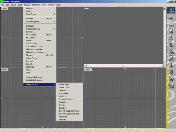
The OpenFX Interface is
shown below with the Actions menu open. It's worth noting that
some of the tools in the right hand toolbar have a second or
expanded function which is activated when you double click on it. Double
clicking the Select tool turns it into a Deselect tool. Double
clicking the Bend tool turns it into a Form tool. Double
clicking the Draw tool turns it into a 3D Plot tool. Double
clicking the Move, Rotate and Scale tools opens popup windows
allowing you enter numeric values for these parameters. |
| |
|
Modeling
Strategy
Draw an outline of the Axe
blade.
Extrude and Scale the
outline to give it shape and depth on one side.
Insert a cylinder into the
blade to fit the handle into.
Mirror the blade to
produce the other side.
Build the handle.
Export the model for use
by other applications.
|
| |
|
Build the Blade
Outline
We're going to
start by drawing the axe blade's outline in the side view
window. We'll draw a quarter of the blade, reflect it to make
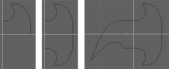
another quarter, and draw the rest. Click
on the Draw tool in the right side toolbar and draw a quarter of the
blade as shown at below left. Make sure all the points are
selected and that the cursor is on the vertex you're going to
reflect around. Click on Actions>Mirror. In the popup
menu that opens, check the box to flip at the cursor "About a
Horizontal Line" and select "Copy, Reflect and
Weld". You should see something like the image at below
center. If you don't, you can press CTRL+Z to undo so you can
retry it. When you're satisfied with the mirroring, draw the
rest of the blade outline. If you start drawing a new curve
from a point on a pre-existing curve, you'll have 2 separate
vertices very close together, one from each curve. To make a
single unbroken curve, you'll need to weld these points
together. Deselect everything by pressing CTRL+D, then use the
Select Lasso from the right side toolbar to select only the
overlapping points. Weld the points by selecting
Actions>Weld. In the popup, type a small value (like 0.01)
for the Threshold Radius and press "Weld". |
| |
|
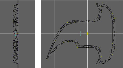
Extrude and
Scale the Blade
Now we're going to start giving the
blade a bit of depth by extruding a surface. Click in the
Rear View window to make that view active. Select everything
using CTRL+A and then click on Actions>Extrude. Start
tapping the left arrow key and you'll see a new set of points
moving away from the originals. Now, select the Scale tool in the right side toolbar
and shrink the new extruded curve down a bit. You'll need to
adjust the positions of the individual vertices to get the new set
to fit completely within the original outline. When you're
done, you should have something that looks like the rear view at
below left and the side view at below right. Don't worry if
the blade looks too thick - we'll sharpen it later.
|
| |
|
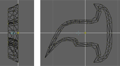
Repeat the
above procedure to produce a second level as shown below. |
| |
|
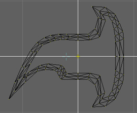
Straighten
the Blade's Centerline We
need a straight line in the middle of our blade where we'll split it
and insert the shaft later. The scaling and moving have skewed
things a bit, so now we get to straighten things out. Make the
side view active. In the middle of the blade where the shaft
will go, the 2 vertices on the original outer curve are sitting on
the vertical axis which is fine. Select the same 2 vertices on
the middle curve and move them to the vertical axis. Do this
with the inner curve and you should have something like the image
below. |
| |
|
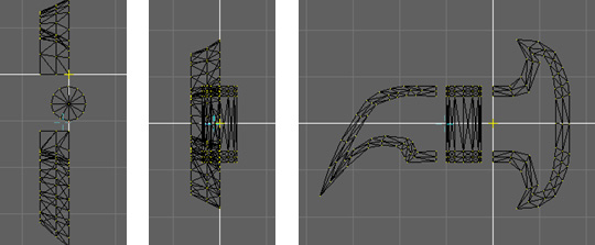
Split Blade
and Insert Center Cylinder Now
we're going to split the blade in half and insert a cylinder through
which the handle will pass. Still in the side view, select all
the vertices from the back of the blade to the middle, including the
ones you just straightened. Duplicate the back of the blade by
clicking Actions>Duplicate and use the Move tool to move the new
vertices completely clear of the original. Deselect
everything, the select the back of the original, up to but not
including the centerline vertices. Delete the selected
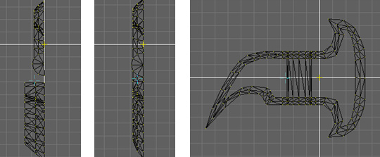
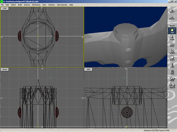
vertices and you should be left with the blade cut cleanly in half. Next,
make the top view active, and create a cylinder by clicking
Build>BuildPrimitives and selecting cylinder. Adjust the
size and position of the cylinder so that it's similar to the image
below. Deselect everything, then select the ring of vertices
at the top of the cylinder. Extrude twice, moving the new
vertices up each time. Repeat this with the bottom of the
cylinder, then adjust the positions of the rings to match up with
the layers of the blade as shown below in top, rear, and side views. |
| |
|
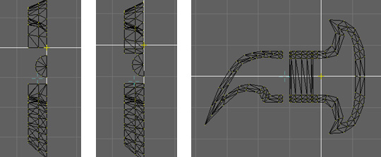
Attach Blade to Center
Cylinder Now
we're going to cut away one side of the cylinder, since we're going
to mirror the whole blade later on. With the top view active,
select the cylinder vertices to the right of the centerline and
delete them, as shown at below left. Next, select the
vertices on the blade front that are facing the cylinder and extrude
them toward the cylinder a little bit. Then select the whole
blade front and move it to the cylinder until the 2 end vertices of
the outer blade outline are touching the corresponding vertices of
the cylinder. Weld the top pair of touching vertices together,
then do the same with the bottom pair. At this point, you should
see something like the top view (below center) and the side view
(below right). |
| |
|
Now we're going
to move the middle and inner blade front outlines so they line up
with the vertices on the cylinder and weld them as we did with the
outer outline. With the top view active, select the whole
center outline of the blade front. Click on the Move tool and
start tapping the right arrow key to line up the middle outline with
the corresponding vertices (the ones at the 11 o'clock position) on
the cylinder. When you're lined up, deselect everything except
the 2 end vertices of the center outline and move them down until they are
touching the corresponding vertices of the cylinder. Attach
the touching vertices by welding. Repeat this process for the
inner blade front outline. When you're done, the top
view should look like the image at below left. Repeat the
process for the blade rear and you'll have something that looks like
the top view (below center) and side view (below right). |
| |
|
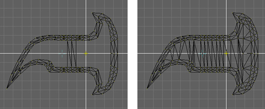
Remove Extra
Cylinder Parts, Fill Surface Since
we'll be producing the other half of the blade by mirroring, we need
to remove the vertices that would produce polygons inside the blade
when it's complete. This is shown in the side view at lower
left. When that's done, fill the inner outline with polygons
by connecting the appropriate vertices with edges as shown at below
right. This is done by selecting a pair of vertices to
connect, then clicking Actions>MakeFaceOrEdge. You can also
use the Fill command, but I can't guarantee you'll get the polygon
arrangement you'll need. |
| |
|
Reduce Blade
Thickness, Add Bolts With
the top view active, select the middle outline of the blade front
and move it toward the centerline. Deselect the vertices
closest to the cylinder and move the remaining selected vertices
closer to the centerline. This will make the blade thinner and
give it a gradual curve. Do the same with the inner outline of
the blade front. Repeat the process for the blade rear to get
something like the top view at below left and rear view at below
center. Next, we add a pair of bolts. With the side view
active, create a Lat Sphere with the BuildPrimitives popup.
Shrink it down, then flatten it out by double clicking Actions>Scale and
setting Left/Right to 0.5. Move it into position so it's
slightly inset into the axe head, then duplicate it. Arrange
the 2 bolts as shown below right. |
| |
|
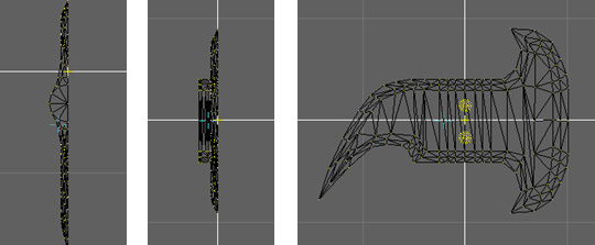
Mirror the
Other Half of the Blade
If you haven't saved already, do so before performing the next
step. With
the top view active, select everything. Make sure the cursor
is on the centerline, then click Actions>Mirror. In the popup
menu, check the box to flip at the cursor "About a Vertical Line" and select "Copy, Reflect and
Weld". You should see something like the top, rear and
side images below. |
| |
|
Add the Top
of the Shaft Now
we're going to make the top of the shaft which is set
into the axe head and protruding from it a bit. Delete the
center vertice in the cylinder at the center of the axe head.
Select the top vertices around the edge of the cylinder. Make
sure everything else is deselected. Place the cursor where the
center vertice was and click Actions>Extrude. Without
moving any vertices, select the scale tool and shrink the selection
a little. Extrude again and move down into the axe head, then
extrude and shrink again. Extrude one more time and move up so the
wooden shaft extends a little bit beyond the metal blade.
Finally, click on Actions>FillOutline to close the top as shown
below. |
| |
|
Add the
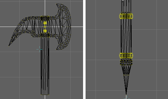
Handle Repeat
the above process to produce the inset shaft protruding from the
bottom of the axe head as shown at below left. Continue
extruding, varying the scale as you go to produce the handle and
spike end. Weld the vertices at the tip of the spike.
Finally, add a pair of toruses form the BuildPrimitives popup menu
to form a couple of iron rings as shown in the image at below right. |
| |
|
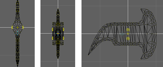
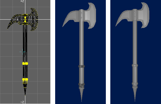
Fix Reversed
Normals The
finished wireframe model is shown in the image at below left.
The Open GL shaded view at below center shows a few areas that
appear black. The normals of these polygons are reversed; they
are facing the wrong way and most rendering engines only render one
side of a polygon to cut computation time. To fix the reversed
normals, select everything, then click on Actions>OrientFaces. This
should get most of the polygons into alignment. If everything
now looks black, then click Actions>Reverse to reverse the
orientation of all the polygons. To correct any stray
polygons, select the vertices where you need to reverse orientation,
then click Actions>Reverse. Your image in OpenFX should now
look something like the image at below right. If you're
satisfied with the model, and want to use it with other programs,
you'll need to export it. Click on File>Export and select
the format you want to use, usually DXF or 3DS. |
| |
|
Where Do We
Go From Here? A Few Options:
Option 1: Keep
it in OpenFX. OpenFX has some texturing and rendering
capabilities. Option
2: Paint the model in an external application. To do this,
export the model from OpenFX as a 3DS or DXF file, then convert it
to OBJ format using Crossroads (free), run it through UVMapper
(free) to get UV coordinates and a template to paint over in the
2D painting application of your choice. You can also use
UVMapper to break the model into groups. Render in Bryce,
Vue, Poser or whatever. Option
3: Group the model and apply procedural textures by group.
To do this, export the model from OpenFX as a 3DS or DXF file,
then convert it to OBJ format using Crossroads (free), and import
it into UVMapper to split the model into groups.
Alternatively, you can import the OBJ file into Poser and use the
Grouping tool to split the model into groups. Next, import
the model into Bryce and apply procedural textures to the
different groups. This is how the picture at the top of this
tutorial was produced. Option
4, 5, 6, 7, 8,..... : anything else you can think of. |
| |
|
Wrapping Up That's
it for this one. Good luck modeling and enjoy the program. Until next time, Chop Chop! |
[RETURN TO TUTORIALS]
Copyright © 2002,
Carl E Schou, All Rights Reserved |