| Building a Boolean
Spacecraft in Bryce
Carl E. Schou
| 1 |
|
Bryce is so easy to
use for landscape generation, that many times its potential for
Boolean modeling is overlooked. With a little preplanning, complex
objects can be created out of simple geometric shapes that would
be difficult to generate in other 3D packages. The subject of this
tutorial is the result of experimentation with Boolean operations
in Bryce and it assumes some familiarity with the program. |
| 1 |
|
Once you have Bryce
up and running, create a sphere. Open the attributes box (CTRL +
ALT + E) and set the position (origin), rotation, and size as
shown in the table below for "Outer Sphere". Also assign
the object’s Boolean properties (P = positive, N = neutral, I =
intersect) as shown. Close the attributes box, then assign the
family number as it is given in the table.
Next create the "Inner Sphere"
using the values given in the table. This sphere can be created
from scratch, or it can be duplicated from the Outer Sphere using
CTRL + D. Finally, create the five cylinders using the values
given in the table.
|
| 1 |
|
| Description |
Family |
Positive Negative Intersect |
X Offset |
Y Offset |
Z Offset |
X Rotation |
Y Rotation |
Z Rotation |
X Size |
Y Size |
Z Size |
| Outer Sphere |
2 |
P |
0.00 |
98.33 |
11.36 |
0.00 |
0.00 |
0.00 |
30.30 |
50.50 |
30.30 |
| Inner Sphere |
3 |
N |
0.00 |
98.33 |
11.36 |
0.00 |
0.00 |
0.00 |
30.00 |
50.00 |
30.00 |
| Cylinder 1 |
6 |
I |
7.50 |
98.33 |
11.36 |
0.00 |
0.00 |
0.00 |
10.00 |
50.00 |
10.00 |
| Cylinder 2 |
7 |
I |
-7.50 |
98.33 |
11.36 |
0.00 |
0.00 |
0.00 |
10.00 |
50.00 |
10.00 |
| Cylinder 3 |
8 |
I |
0.00 |
98.33 |
18.86 |
0.00 |
0.00 |
0.00 |
10.00 |
50.00 |
10.00 |
| Cylinder 4 |
9 |
I |
0.00 |
98.33 |
3.86 |
0.00 |
0.00 |
0.00 |
10.00 |
50.00 |
10.00 |
| Cylinder 5 |
10 |
N |
0.00 |
85.83 |
11.36 |
0.00 |
0.00 |
0.00 |
30.00 |
25.00 |
30.00 |
|
| 1 |
|
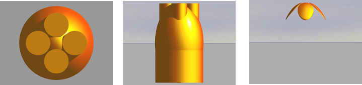
Select all the
objects then pick the "warm gold" material preset. It’s
in Edit > Materials > Simple & Fast (Row 3, Column 1).
If everything’s good so far, a test render from the top view
should look like the image below on the left. A render from the
right view is shown in the center. With the seven components still
selected, group them together. If your render from the right view
looks like the image below on the right, then assign the group to
family 11 with the name "4petal1". If your render looks
wrong, you’ll want to ungroup the objects and back track and
find the problem before continuing. If your render looks right,
now is a good time to save your work. |
| 1 |
|
 |
| 1 |
|
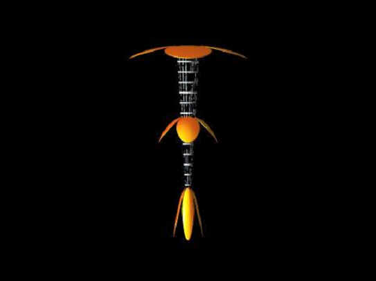
Now you have the
midsection of your spacecraft constructed. It should have the
values given in the table below for the object 4petal1. To build
the aft section (4petal2), select 4petal1, duplicate it using CTRL
+ D, and set the values given for 4petal2 in the table. This
creates an aft section twice as wide and half as long as the
midsection. Repeat the process to build the bow petal section
(4petal3). This creates a bow section half as wide and twice as
long as the midsection.
To build the structure connecting the
three sections, create a cone using the values in the table for
"body cone". For the cone I used the "steel
cage" preset in Edit > Materials > Miscellaneous (Row
4, Column 3). This material controls transparency to create a
complex looking structure out of a single object. The size of this
material was tweaked in the materials editor to 80% for x, y, and
z since the original values of 40% didn’t give fine enough
detail.
To set the scene, I went into Sky&Fog
and selected the Simple Black Background (Row 4, Column 4). The
ground plane was selected and deleted. When this is done, your
render from the right view should look like the image following
the table below. |
| 1 |
|
| Description |
Family |
Positive Negative Intersect |
X Offset |
Y Offset |
Z Offset |
X Rotation |
Y Rotation |
Z Rotation |
X Size |
Y Size |
Z Size |
| 4Petal1 |
11 |
P |
0.00 |
98.33 |
11.36 |
0.00 |
0.00 |
0.00 |
30.30 |
50.50 |
30.30 |
| 4Petal2 |
12 |
P |
0.00 |
140.96 |
11.36 |
0.00 |
0.00 |
0.00 |
60.60 |
25.25 |
60.60 |
| 4Petal3 |
13 |
P |
0.00 |
43.08 |
11.36 |
0.00 |
0.00 |
0.00 |
15.15 |
101.00 |
15.15 |
| Body Cone |
14 |
P |
0.00 |
113.01 |
11.36 |
180.00 |
0.00 |
0.00 |
10.00 |
80.00 |
10.00 |
|
| 1 |
|
 |
| 1 |
|
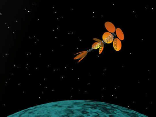
To make the craft
into a single object, group the four components (families 11, 12,
13, 14) and assign them to family 15 under the name "Petal
Ship 1". Set the X rotation in the attributes box to 60
degrees as shown in the table below. You shouldn’t have to touch
the other values for Petal Ship 1. Go into the SkyLab and turn on
the Starfield with an intensity of 50 and an amount of 2800 or so.
Create a sphere with the values for "Planet" in the table
below. For the planet I used a variant
of the "Flowing Contortions" preset called
"Swirlwave". With the sphere selected,
go into the Texture Editor,
select Texture Library > Basic > Swirlwave. Set the view to
Director and render. If all has gone well, you should get an image
like the one below. The camera position I used was x=-102.40,
y=30.72, z=102.40. The rotation in y was 135 degrees. |
| 1 |
|
| Description |
Family |
Positive
Negative Intersect |
X Offset |
Y Offset |
Z Offset |
X Rotation |
Y Rotation |
Z Rotation |
X Size |
Y Size |
Z Size |
| Petal Ship |
15 |
P |
0.00 |
73.08 |
11.36 |
60.00 |
0.00 |
0.00 |
60.60 |
161.00 |
60.60 |
| Planet |
16 |
P |
0.00 |
-240 |
0.00 |
0.00 |
0.00 |
0.00 |
500.0 |
500.0 |
500.0 |
|
| 1 |
|
 |
| 1 |
|
As an alternative,
you could download an image of a planet from one of the Voyager
missions to spherically map onto your planet. You could also
replicate the craft to generate an armada in the distance.
Good luck and Enjoy. |
[RETURN TO TUTORIALS]
Copyright © 2000, Authors Name,
All Rights
Reserved |