Build a Sea Scorpion
with Subdivision Surfaces in Carrara Studio 2
Carl E Schou
October 31, 2002
| |
|
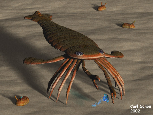
The Crawdad of
the Apocalypse
The picture shown above is
dedicated to anyone who enjoys dining on lobster, Crawfish Ettoufe,
or seafood in general. It is a prehistoric Sea Scorpion and it
is the subject of this month's entry into the digital domain.
We will start with a quick
look at Subdivision Surfaces and how they are implemented in
Carrara. We will also cover some background on the Sea
Scorpions before we begin the modeling process. |
| |
|
Subdivision
Surface Modeling
One of the new features in Carrara
Studio 2 is Subdivision Surfaces. This is a modeling technique that allows the user to build a complex surface
using a simplified wire-frame model, whose vertices act as control
points. The name Subdivision Surfaces derives from the fact
that they are based on the binary subdivision of the uniform
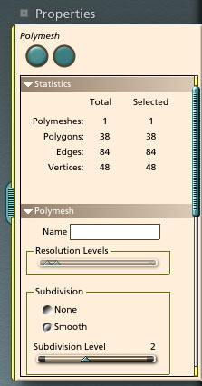
B-spline curves and surfaces. In
Carrara, Subdivision Surfaces are turned on from within the Vector
Modeling room. All you need to do is to select your model,
open the Polymesh section of the Properties tray at the right side
of the screen, and click the button labeled "smooth" in
the Subdivision section as shown below. |
| |
|
Background on
the Sea Scorpions
The Eurypterids, also
known as Sea Scorpions, were primitive arthropods whose closest
living relatives are the scorpions. They lived approximately
400 million years ago and ranged in size from 10 centimeters (4
inches) to over 2 meters (6.5 feet) in length, making them one of
the biggest predators of their day. One of the largest known
species is called Pterygotus buffaloenisis, and that's what we'll be
modeling here. |
| |
|
Sea Scorpion
Modeling Strategy
Before beginning work on
this project, it is recommended that you read through this tutorial
so that you will know where each step is heading. Some
reference images can be found on the internet by following the links
given at the end of this tutorial. To
create our Sea Scorpion, we will build a simplified wireframe model
in the Vertex Modeling room with Subdivision Surfaces turned
on. To get the insect-like segmented effect, we will tuck each
body part slightly inside the next body part, being careful to avoid
overlap. We will start with the body, building it segment by
segment, then add the tail, the head, the compound eyes, the
flippers, the legs, and the pincers. The last part to be
added will be the simple eyes. Only one object will be built
for each type of part. For example, a single leg will be
built, then duplicated with scaling and symmetry to get all eight
legs. |
| |
|
Building the
Body
To begin, we open Carrara
and start a new document. Create a vertex object by dragging
the vertex symbol into the Assemble room workspace. This will
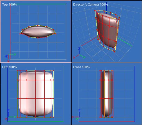
put you into the Vertex Modeling room. Now create a circle
with 12 vertices. If you're set up for the quad view, the
circle will be facing you in the Top view. With the whole
circle selected, scale it down in the X direction to get an oval
shape. Select just the bottom 5
vertices and
move them up a little as shown in the Top view of the image below.
Next, select all 12 vertices and extrude them upward for a distance
of 2 units. Extrude them again for 2 units, then extrude them
for 1 unit. You should see something like the image below. |
| |
|
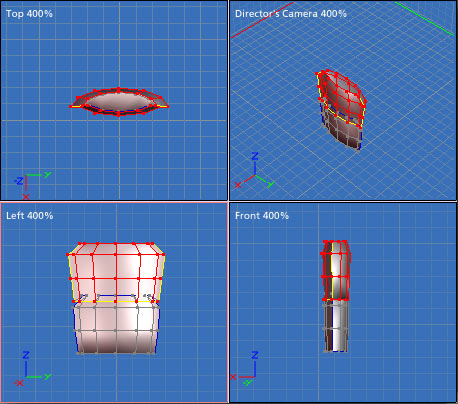
Now we are
going to scale down and shape the first body segment a bit and then add the second
segment. With everything selected, scale the model down to the
size shown in the Top view of the image below. Hold down the Alt key while scaling to lock the
XY scale. Any scaling done in this tutorial will be done this
way unless otherwise noted. Using the Left view, select and
scale each of the four rings of vertices until it looks like the grayed-out
(unselected) portion of the model in the image below.
Next, we add the second body segment
by extruding it from the first. Select the top ring of points
and extrude them downward for a short distance. Enlarge these points to get them back to their
original size and extrude upward. Enlarge them and
extrude them upward again, then extrude them upward for a short
distance.
Shrink the new top ring of vertices down about 85%. You should
see something like the image below. Note that for this image,
the second body segment is selected for illustration purposes.
|
| |
|
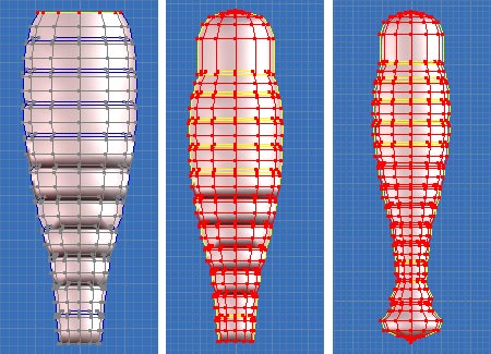
Continue the
sequence described above to build the body as shown below left.
The head has been added in the image below center and the tail has
been added in the image below right. Remember not to leave an
open tube at either end of the body. Scale the vertices down
to nearly a point, then weld them together. |
| |
|
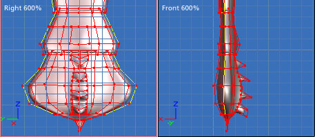
Giving Detail
to the Tail
The tail, or telson, of this species of
Sea Scorpion had short spikes running down the top centerline.
To model these, we need to increase the control mesh density by
adding vertices to the model as shown below. This may be done
using the Add Point tool, or by selecting two adjacent points, then
clicking Edit>Subdivide. When you have the extra needed
points, connect them by adding edges. This is done by
selecting two points and pressing CTRL+Shift+L. If you have
difficulty selecting only two points, you can deselect the extra
points by holding down the ALT key while moving the select marquee
over them. |
| |
|
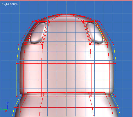
Adding the Eyes
To make an eye, select a
rectangle where you will want the eye to be located. Extrude
it outward a short distance and scale it down a very small
amount. Extrude inward a little farther than the first
extrusion and scale it down again. Extrude it outward a
greater distance and scale it down again. Repeat this process
for the other eye and the result should look like the image below. |
| |
|
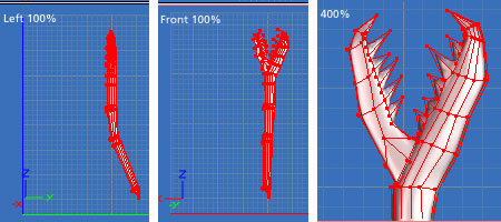
Building the
Flippers
To build the back flipper,
we take one of the cross-sections from the body and repeat the
process of extruding and scaling as shown below. Remember to
articulate the joints by using the same tucking process we used for
the body. |
| |
|
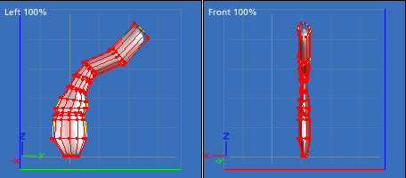
Building the
Legs
To build a leg, we again
start with a cross-section from the body. This is scaled up in
the Y direction to make it rounder. You will see there are two
pairs of tucked vertices which will form a seam we don't want along
each edge of the leg after extruding. Select one pair of the
vertices and weld them together. Repeat the weld for the other
pair of vertices. Now perform the same scaling and extruding
process to create the leg. |
| |
|
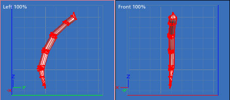
Building the Pincers
To build the pincer, start
from one of the cross-sections developed for the leg. When you
get to the joint in the claw, perform the same trick of extruding
in, scaling down, and extruding out to give the appearance that the
smaller claw part is inset into the larger. Add the spikes on
the inner edges of the claws using the same process that was used
for the spikes on the tail. |
| |
|
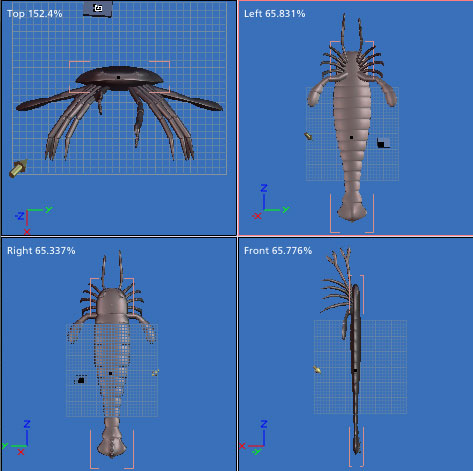
Putting it All Together
Now comes the fun part,
putting it all together. Go back into the Assembly room and
start adjusting the sizes on the body, flipper, leg, and
pincer. Using the Properties Tray, make sure that the body is
centered at Y = 0.0. Move and rotate the flipper into position
on one side of the body as shown. Then use the Duplicate With
Symmetry function in the Edit menu to mirror the flipper around the
Y axis. Repeat this process with the pincer in the front of
the body. Select the leg, then move and rotate it into
position on one side of the body and Duplicate it three times.
Apply a bit of scaling so that the legs get smaller towards the
front of the body. Now use the Duplicate With Symmetry
function around the Y axis on each leg to produce a total of eight
legs. To save yourself headaches later on, you will probably
want to rename each part in the Properties Tray as you go. The
last part to be added is the pair of simple eyes in the middle of
the top of the head. In the Vertex Modeling room, create a
sphere. Back in the Assembly room, scale it down to make it
tiny, and inset it into the top of the head a little off of
center. Duplicate with Symmetry and the simple eyes are done. Open
up the Sequencer Tray at the bottom of the screen and make all of
the other parts children of the main body part. This may be
done by dragging each part onto the main body part in the Sequencer
Tray. |
| |
|
Finishing
Touches
When you see the parts all
together, you will probably notice things that need adjusting.
If a problem exists in all of the legs, you don't need to adjust
every one of them. Simply edit one of them as a Master object,
and any changes you make will be carried over to all of the
duplicates. |
| |
|
Exporting
Your Model
If you plan on applying
textures and rendering your images within Carrara, then exporting
your model is not an issue. Indeed, Carrara's rendering engine
with Global Illumination really can't be beat. However, if you want to use your model
with other 3D applications, you will find that the Subdivision
Surfaces mesh does not export from Carrara as easily as do the other
model types. There are currently two ways to export a
Subdivision Surfaces mesh from Carrara.
The first exporting method
is done entirely within Carrara. Select a part of the model in
the Assembly and go into the Vertex Modeling room. In the Edit
menu, click ConvertToOtherModeler and select Primitive for the model
type. Again, click ConvertToOtherModeler and select Vertex for
the model type. Repeat this process for each part of the
model. When you are done, select all of the parts and export.
In the second exporting
method, the simplified wireframe control point
model is exported from Carrara and imported into another
program. This second program regenerates the Subdivision
Surfaces mesh, then exports the mesh. A free and easy way to
do this is by using the Anim8or program, following the steps given
below:
(1) Export the simplified
wireframe control point model from Carrara as an OBJ file by
selecting the model and clicking File>Export filename.
(2) Import the model into
Anim8or by clicking Object>Import filename.
(3) Click on
Build>ConvertToSubdivided.
(4) Click on
Build>ConvertToMesh.
(5) Click on Object>Export
newfilename.
Viola, you have an
exported mesh ready for use in the app of your choice.
|
| |
|
The Rest of
the Picture
To produce the
picture "The Crawdad of the Apocalypse", the Sea Scorpion mesh was
exported as an OBJ file using the second process given above. It was
imported into Poser 4 for grouping (eyes and body). The
Jellyfish was modeled in Carrara using the Spline modeler for the
tentacles and the Vertex modeler with Subdivision Surfaces for the
body. The stalk
eyed Trilobites were modeled in Organica and grouped in Poser.
The models were then imported
into Bryce for texturing and rendering. So
good luck with this project and I hope you enjoy it as much as I
did. Right now, I've got a sudden craving for seafood,
especially lobster... |
[RETURN TO TUTORIALS]
Copyright © 2002,
Carl E Schou, All Rights Reserved |