| Unwrap3D Tutorial:
UV Mapping a Sailing
Ship (or Anything Else)
Carl E. Schou
September 2004
| |
|
The Santa Maria
In our previous tutorial, we built a model of Columbus' ship, the
Santa Maria using Amapi 7 Pro. For this month's installment,
we are going to UV map and texture that model using
Ultimate Unwrap3D and Photoshop. The concepts and techniques
used in this tutorial are applicable to a wide variety of different
types of models, not just to sailing ships. For anyone wishing
to review the construction of the Santa Maria model, a link is provided in the
Related Links section at the end of this tutorial.
We will start
with a quick look at what UV mapping is, followed by the strategy
for this project, and some tips on making models easier to UV map, before starting the actual work. |
| |
|
What is UV Mapping
UV coordinates are the “pins” used
to attach a texture to a model, and UV mapping is the process of
applying UV reference coordinates to a 3D model. These coordinates
are used as a reference that controls how a flat 2D texture image
will be wrapped around the model. You can choose mapping methods
such as spherical or cylindrical that are closest to the original
shape of your model but will probably produce some distortion.
The art of UV mapping involves adjusting the position of the UV
coordinate on the map to minimize this distortion. |
| |
|
Strategy for UV Mapping a Model
(1) Build, borrow, or download a model that you want to UV map
and texture.
(2) Import the model into UnWrap3D and UV map the entire model
using the mapping that best fits the model. For this project,
single-sided planar mapping was used.
(3) If the model does not already have a material, create one in
UnWrap3D. Load a reference texture into this material to get
visual feedback when adjusting the UV points to minimize the distortion
in each group.
(4) Start with the simplest mapping first. Map the parts
oriented along the X, Y, or Z axis that need Cylindrical, Spherical,
or Planar UV mapping.
(5) Map the off-axis parts that need Cylindrical, Spherical, or
Planar UV mapping by using the Interactive Mapping tools.
These allow you to rotate the UV reference to align it with the
part.
(6) UV map the irregularly shaped objects using the mapping that
fits the best, then adjust the UV points to minimize texture
distortion.
(7) Apply Box mapping to cube or box shaped structures, and
manually align the maps where needed.
(8) Pack the map to get the most efficient use of space.
(9) Make your texture map and load it into the model's material.
Readjust UV points if needed.
(10) Export the UV mapped model in a format such as OBJ needed by
your rendering application.
|
| |
|
Modeling Considerations
Some models are relatively easy to UV map, and their textures are
easily recognizable. You can look at the texture map be able
to tell how the map will fit to the model. Other models are
nearly impossible to make distortion free without applying
techniques that unwrap the UVs or break up the maps into small
sections, producing textures that are difficult to recognize or use without
resorting to projection painting 3D texturing programs. Here are a
few tips for making models that are easy to UV map, and that can be
textured with images right out of Photoshop.
Keeping the polygon count down can be a big help. Since the
distortion is tuned out of a mapped texture by moving the UV points
that correspond to existing vertices, keeping the polygon count down
to a reasonable level goes a long way towards keeping a UV map
manageable. UnWrap3D has a Soft-Select option that allows for
the editing of multiple points, but it is still simpler to move
a single point than a large number of them.
A model with a complex shape that is a single group can be very
difficult to map without distortion or splitting of the map.
Slicing the model into simpler shaped groups can simplify things
greatly, and allow the use of basic mapping shapes with little
distortion to correct. If the borders of the groups correspond
to seams in the model, it is that much easier to hide the breaks in
the texture.
The neater the model's mesh, the neater the UV coordinates.
If you have a choice between using four point facets (quads) or
three point facets (triangles), the quads are usually the better
choice. Whatever the facet shape, having all of the sides
close to the same length will help to minimize distortion.
Long thin facets, especially triangles, can produce texture
distortions that are nearly impossible to tune out.
Keep parts relatively straight before mapping. It can be tedious to map an
object that keeps changing its orientation. To make life
easier, build the model with the parts aligned along the X, Y, or Z
axis, then apply UV mapping, then use your modeling program to put
the bends and twists into your model. An example of this
approach is the flag in this model. It was modeled flat, then
planar UV mapped, then shaped as though it were flapping in the
wind. When the texture was applied, it followed the bends and
turns turns in the flag with no distortion. |
| |
|
UV Map the Entire Model to get
Started
If your model does not already have UV coordinates, then the
first thing you will want to do after importing it into UnWrap3D, is
to give it some. We are going to assign a single sided planar
UV mapping to our model. Later on, the mapping of some parts
will be adjusted, or they will be re-mapped using Cylindrical,
Spherical, or Box
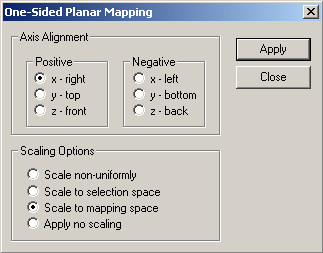
mapping. To apply the first mapping, select the entire model, then
click on 2D Tools > UV Mapping > Planar > One Sided as shown below. |
| |
|
The pop-up window should open as shown
below. Set the Axis Alignment as needed to match the
orientation of your model. |
| |
|
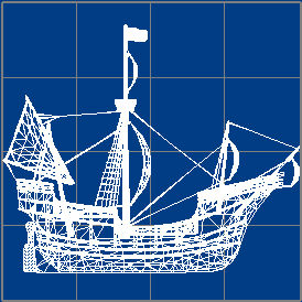
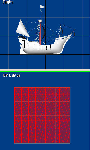
The resulting UV coordinates of all
groups of the model are shown below in this screenshot from the UV
Editor window. |
| |
|
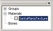
If your model does not already have a
material assigned, you can create one by selecting the entire model,
right clicking on Materials in the Scene window, selecting Add to
add the material, then right clicking again to Rename it as shown
below. Later on, we will be adding a checker pattern to the
material to use as reference texture for minimizing distortion,
before applying the final texture maps. |
| |
|
Isolate Groups to Make an Uncluttered
Work Area
The easiest way to work on any single
part of a multi part model is to select all of the other parts, then
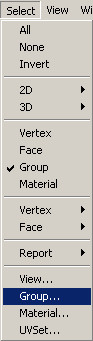
move them out of the way to get a clear work area. To do this,
click on Select > Group, making sure you choose the second mention
of Group in the drop down menu as shown below. |
| |
|
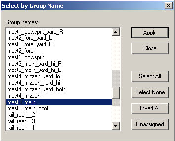
In the pop-up window that opens, scroll
down and select the one group you want to remain unselected as shown
below. To select all of the other groups, click Invert All,
then Apply, the Close. For our purposes, we are going to start
with the ship's main mast, so we will select that, then invert the
selection to select everything else. |
| |
|
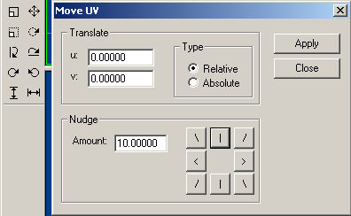
To move the selected UVs off the map,
activate the Move UVs tool by clicking the symbol with the four
arrows on the left side of the screen. In the pop-up window
that opens, enter a large, easily remembered value for the Nudge
Amount, then click the button for the direction you want to move it
as shown below. By sticking with the same value for the Nudge
Amount, you can easily move UV for any group into or out of the work
area without having to zoom out your viewpoint and hunt for the
parts. |
| |
|
UV Map the On-Axis Objects
Now that the map area is clear of all the UVs except for those
from the group you are planning to map, it is time to invert the
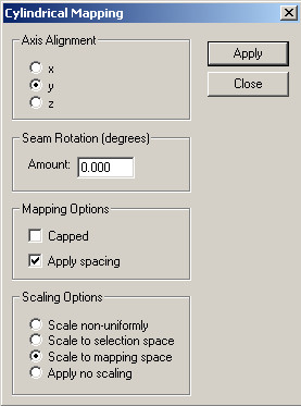
selection by clicking Select > Invert. In this case, the main
mast of the model is selected. This part is easy to UV map
since it is oriented along the vertical axis. Click on 2D
Tools > UV Mapping > Cylindrical to open the window shown below.
Set the Axis Alignment to Y and press Apply to generate the UV map. |
| |
|
The resulting UV map of the selected
main mast group should appear as shown below. The facets in
the UV map correspond to the facets in the model, unwrapped from
their cylindrical shape and laid out flat. Repeat this process
with the other masts that are oriented on-axis. |
| |
|
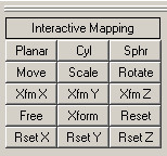
UV Map the Off-Axis Objects
Most of the masts on this model are oriented along the X, Y, or Z
axis, so they are easy to cylindrically map by setting the axis of
alignment to the appropriate axis. The masts that are at an angle may still
be cylindrically mapped, but the orientation of the mapping needs to
be rotated to line up with the selected object. This is done with the
Interactive UV Mapping option. To use this, click Window >
Interactive to bring up the menu as shown below. |
| |
|
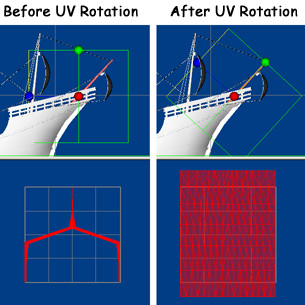
Clicking on Cyl in the Interactive
Mapping menu should produce something like the two images below
left. The 3D modeling window will show a cylinder with red,
green, and blue control handles centered on the selected part of the
model. The UV map at lower left is badly distorted.
To
rotate the UV reference, go back to the Interactive Mapping menu and
click on Rotate, then on XfmX to constrain the rotation to the X
axis. Click and drag in the 3D window to adjust the rotation.
When you have aligned the UV reference with the object, the UV map
should straighten out as shown below right. |
| |
|
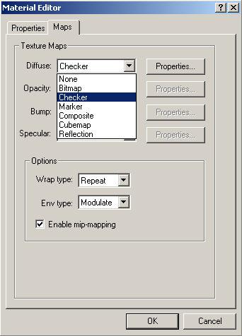
Apply a Reference Texture to
Visualize the Distortion
The next part of the model to be mapped is the ship's hull, and
it is the part that will require the most work to minimize any
texture distortion due to its irregular shape. The easiest way
to see the distortion is to use a reference texture. To apply
this texture, double click on the name of the material in the Scene
window to open up the Material Editor as shown below. For the
Diffuse channel, select Checker. |
| |
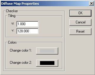
|
Click on Properties and set the sizes
for the tiling as shown below. This should stretch the cubes
enough that they almost appear to be horizontal stripes. |
| |
|
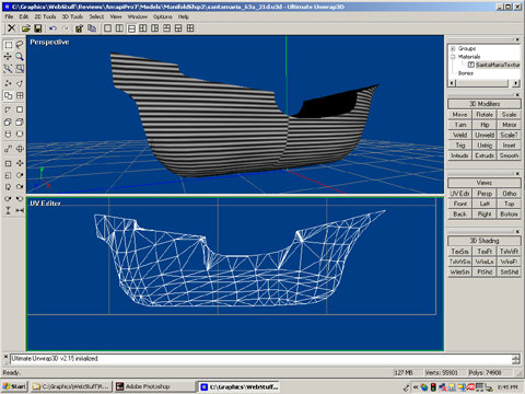
Minimize Distortion in Irregularly
Shaped Objects
Now that a striped reference texture has been applied to the
model, move any other groups out of the area, leaving a clear
workspace to map the ship's hull. In the upper Perspective
view of the screenshot below, all parts except the hull have been
hidden. The UV mapping seen in the lower UV Editor window is
the original single sided planar mapping that was applied to the
model at the start of the project. Notice that the reference
texture looks like it was projected onto the hull with a slide
projector. It does not follow the sweeps and curves of the
ship's hull. Though it is not visible in this screenshot,
extreme texture stretching was also occurring along the bottom of
the model. |
| |
|
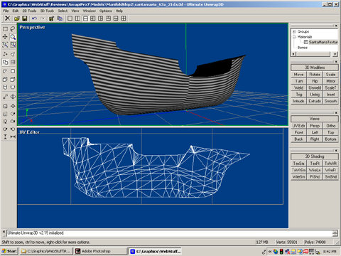
The screenshot below shows the result of
moving the UV points in the lower window to minimize the distortion
seen in the upper window. While this tuning was being done,
the orientation of the stripes was occasionally changed from
horizontal to vertical
by switching the values given to the U and V tile sizes in the
Properties window. |
| |
|
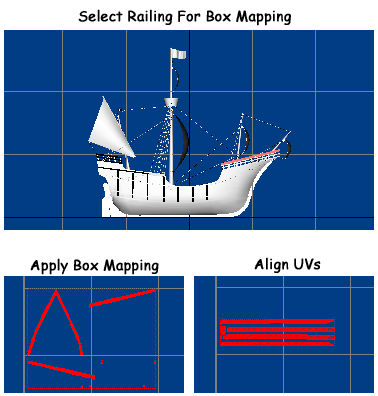
Apply Box Mapping to Any Box-Like
Surfaces
This model has quite a few parts, such as railings and square
posts, which are good candidates for Box (or Cubic) mapping as is
shown below. After selecting the top railing, Box mapping was
applied to the groups as shown below left. The different
pieces of the map were then rotated to bring them all into alignment
as shown below right. The purpose of the alignment is to
ensure that the wood grain image will map in the same direction
along all faces of the railing. |
| |
|
The Rest of the Mapping
The deck was planar mapped in sections with the axis alignment
adjusted to match each section's orientation. The sails were
planar mapped and their UV points were straightened so that textures
applied would billow out naturally with the shape of the sails.
The Crow's Nest was Cylindrically mapped. To add the flag, the
model was imported into Carrara where a flat flag was built and
grouped with the ship. Back in UnWrap3D, the flag was Planar
mapped, and the model's material was re-created to incorporate the
flag. The model was then taken back into Carrara where wave
modifiers were applied to the flag to give it an appearance of being
in the wind. |
| |
|
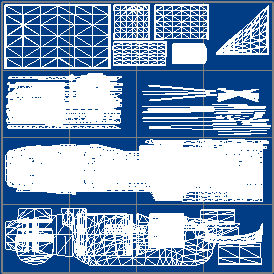
Packing the UVs Inside the Template
Once all of the parts have been mapped, it is time to move them
all into the UV working space, and arrange their sizes and positions
to make the most efficient use of the available texture area.
The working space is the white box in the UV Editor window.
Usually, you never want to let the positions of the individual maps
overlap, so that each part of the model will have its own unique
texture. However, this
model had a great many parts, so texture overlapping was permitted
in the parts with similar textures. Offsetting the positions
of the different groups introduces an element of randomness, and
keeps the different textures from looking like clones.
The UVs for the different
groups were scaled and arranged in areas of the map as shown below.
When the arrangement was complete, the UV Map was exported and used
in Photoshop as a template for making the color and bump texture
maps. |
| |
|
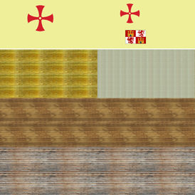
The texture map for the color channel is
shown below. The top quarter of the map is used for the sails
and the flag. The next quarter is split between the light wood
texture on the left for the wooden railings, and the rope texture on
the right. The third quarter is for the darker wood used in
the ship's keel, masts, and support beams. The bottom quarter
is made up of a plank texture used for the body of the ship.
The wood and rope textures, which came from 3dStudio.com, were tiled
to fill out their respective areas in the texture map. |
| |
|
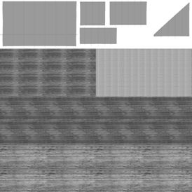
The texture map for the bump channel
shown below, is a grayscale version of the color map, except for the
sails which have faint creases added to show the sections of the
sails that have been stitched together. |
| |
|
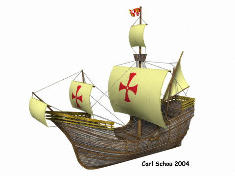
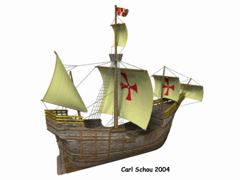
A parting shot of the finished model is
shown below. This image, and the image at the start of the
tutorial were rendered in Carrara Studio 3. |
[RETURN TO TUTORIALS]
Copyright © 2004,
Carl E Schou, All Rights Reserved |